Challenge description: While sitting on my back porch, I noticed a strange signal and made a SigMF recording. Can you make any sense of it?
The challenge gives us a binary file containing a signal never_the_same_color.sigmf-data as well as a file containing its metadata never_the_same_color.sigmf-meta in SigMF format.
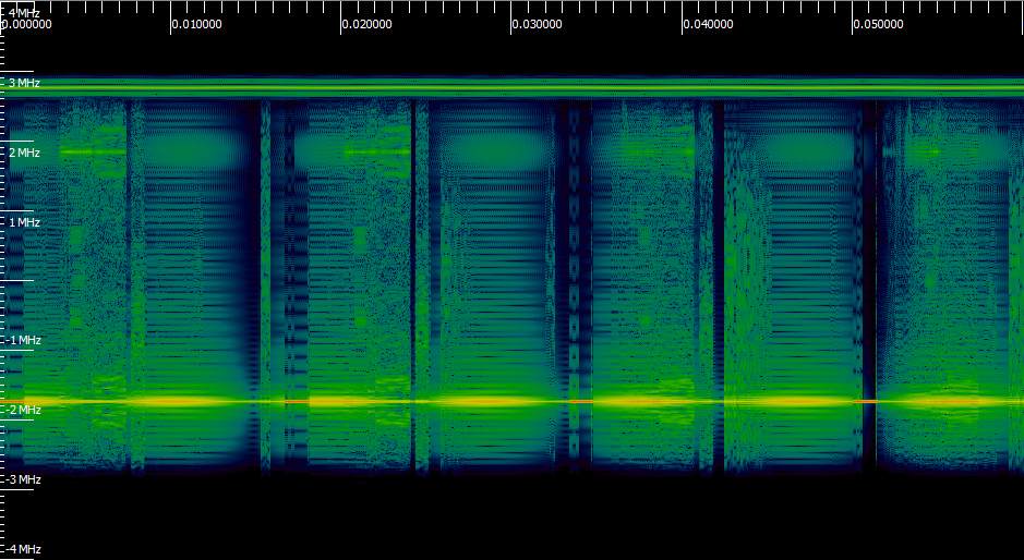
Let's open it with Inspectrum:
We have a signal that's about 6MHz of bandwidth. According to the metadata, we know it's a complex signal sampled at 8MHz. Not much idea about the type of signal, but searching the web for the challenge name Never the same color, we find NTSC, a video broadcast standard. Browsing the Wikipedia page, we see that an NTSC signal has a bandwidth of 6MHz, so we're on the right track :)
The signal contains several components to form an image and sound. To make things clearer, I roughly redrew the diagram from the Wikipedia page but with our signal:
Knowing that we have 7 flags to find, they're probably spread across the different components of the signal. I didn't find them in order, so it's normal that it doesn't start with Flag 1.
Flag 2
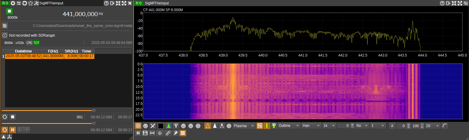
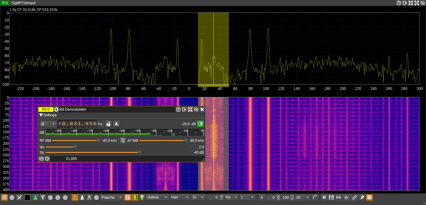
Let's start simply by opening the signal with SDRangel which has a plugin to decode ATV signals, including NTSC.
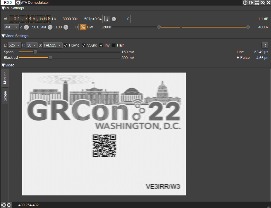
First, we apply the ATV Demodulator, then, since we know the video signal is amplitude modulated, we choose AM. You can also already check Hsync and Vsync because for a TV image, the image is displayed line by line, from left to right, then top to bottom. So, to keep track, the signal must know when a line (Hsync) or all lines (Vsync) end. By enabling these two options, we tell the plugin to use these pulses in the signal to properly reconstruct the image.
Okay, we see the start of an image with a QRCode that can't be scanned yet, so we'll need to keep configuring this plugin.
First, we can set the center frequency to the video carrier at about 439.25MHz. Then, AM generates 2 sidebands containing the same information: one above the carrier called the upper sideband (USB) and one below called the lower sideband (LSB).
Each sideband is 4.2MHz wide, so if we transmitted both, it would be 8.4MHz total. So, to save bandwidth, NTSC keeps all of the upper band and only a small part (1.25MHz) of the lower band, which is called a vestigial sideband (vestigial sideband).
So, to handle this, we enable the asymmetrical filter (FFT asymmetrical filter button) which will help us better extract the image, taking into account that our signal isn't symmetrical since we have a vestigial sideband.
There are 2 sliders on the right to adjust the filter, the Opposite band cutoff (lower band) and the In band cutoff (upper band). Together, they'll give us the perfect spectrum range to get a stable and readable image.
In our case, we can set the Opposite band cutoff to 1200kHz (1.25MHz) and the In band cutoff to 4200kHz (4.2MHz).
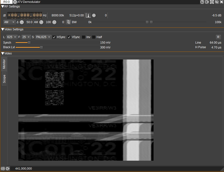
Finally, for the video parameters, again thanks to Wikipedia, we can fill them in as follows:
L (Number of lines): 525
F (FPS): 30
S (Sync format): PAL525 (because the sync is on 525 lines)
Also, I had to enable Invert video so the image would be sharp and not flicker.
By the way, don't hesitate to hit the stop button and then restart the signal, sometimes that helps.
This plugin can be finicky, so if it doesn't work for you, restart it, try changing the order in which you set things up.
Cool, we can scan the QRCode, except... It's a nice RickRoll. Looking closer, we can see that our video signal, although it appears static, has a frame that seems to change at about 3s, altering the QRCode. Let's extract the frames from this video.
And here, I honestly don't know how to do it with SDRAngel, so I recorded a video of my screen around 3 seconds, then with this site I extracted 100 frames every 10ms until scrolling to find THE frame with the different QRCode containing the flag for Part 2: flag{2OBGfE29cR1SpOXuJpI832FyAWvNPLtC}!
Flag 1
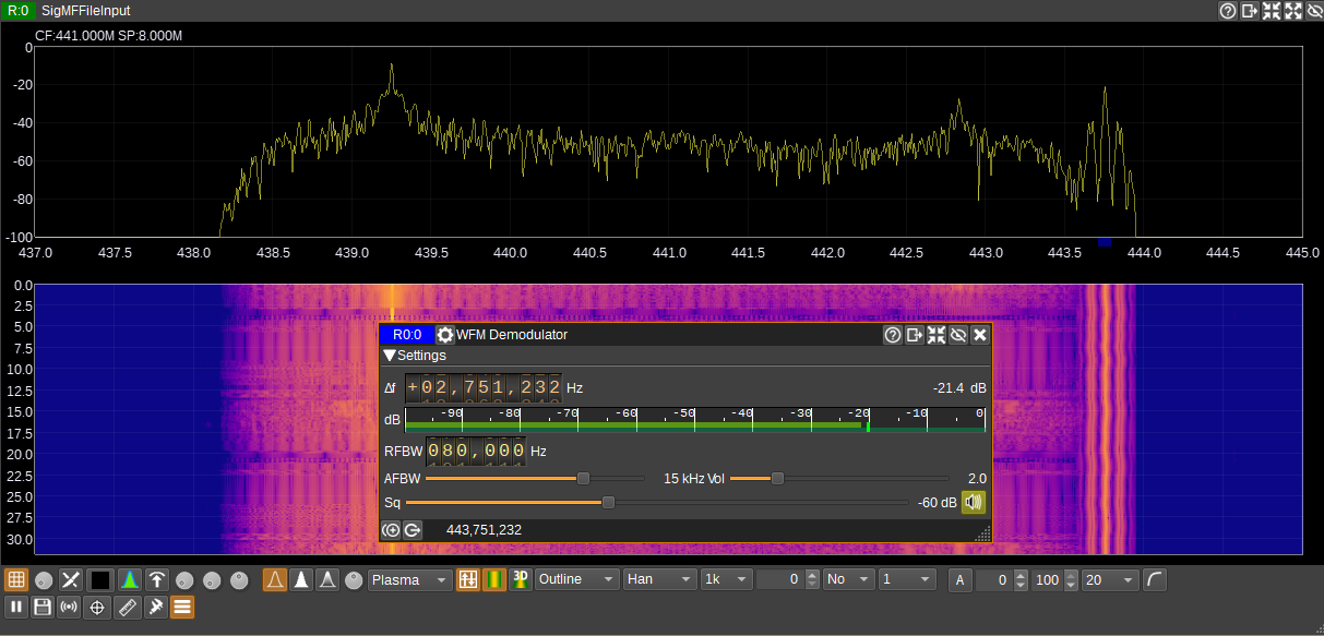
In NTSC, the audio signal is frequency modulated (FM) with a frequency deviation of 25kHz. Out of curiosity, to estimate the bandwidth of this signal, we can use Carson's rule, which tells us that the bandwidth of an FM signal is ≈2(Δf+fm), where Δf is the frequency deviation and fm is the maximum frequency of the audio signal (often 15kHz for audio content). So applying the formula, it would be ≈2(25kHz+15kHz)=80kHz.
Let's add a WFM Demodulator block.
We set the center frequency to the audio peak on the right, zooming in to be more precise, and everything is already well configured so we can hear a voice giving us the flag for Part 1: stream.
Flag 3-4-5
On Wikipedia, it also mentions that the audio signal can contain an MTS (Multichannel Television Sound) signal, and it's true that when we look at our audio spectrum, we see several peaks in addition to the center frequency. In fact, MTS allows adding stereo, a second language (SAP), or other audio channels.
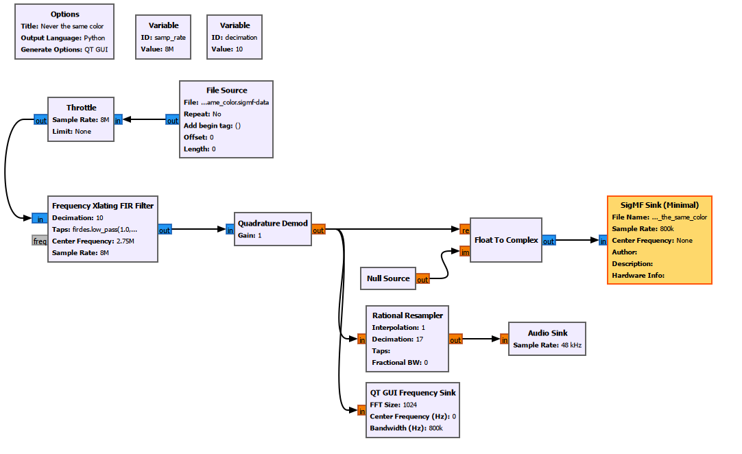
The thing is, we need to work on our signal after FM demodulation; otherwise, it's super complicated to clearly hear the different flags. SDRangel doesn't allow saving a demodulated signal in complex format (or I don't know how), so to keep it simple, I cropped the audio part, demodulated it in FM, and saved it in a new file with GNURadio:
The Frequency Xlating FIR Filter block will shift and filter a signal to keep only a range that suits us.
Our audio signal is about 400Khz wide and is roughly located at +2.75MHz, and instead of keeping a sampling rate of 8MHz, we'll perform a decimation of the signal, reducing its sampling rate to be more precise.
To determine the decimation factor, we use the Nyquist-Shannon theorem, which basically tells us that the sampling rate must be at least twice the bandwidth of the signal. So for an audio signal of 400Khz, we can decimate it to 800kHz, which is a factor of 10 (8MHz/10=800kHz).
Next, the Center Frequency is set to 2.75MHz, representing the audio signal's carrier. The filter will use this center frequency for filtering.
Finally, the filter coefficient (taps):
firdes.low_pass(1, samp_rate, 200e3, 100e3)
firdes.low_pass -> Low-pass filter that only allows frequencies below a certain limit (cutoff frequency) to pass and blocks those above.
1 -> Filter gain, here we set it to 1, meaning we don't modify the signal's amplitude (no amplification or attenuation).
samp_rate -> Input signal's sampling rate, so for us, 8MHz.
200e3 -> Filter cutoff frequency after decimation, we want a 200kHz band around the center frequency (2.75MHz).
100e3 -> Filter transition zone, so we'll have 100KHz that are gradually attenuated around the areas to be eliminated rather than abruptly cut. This is just to avoid distortions or anything.
Next, the Quadrature Demod block will allow us to frequency demodulate the audio signal, which, as a reminder, is FM modulated. The gain is set to 1 because we don't want to amplify or attenuate the signal.
This block transforms the complex signal into a real signal, but we want to save it in SigMF format to reopen it with SDRangel, so we need to convert it back to complex with the Complex to Real block.
We don't want an imaginary part, so we'll set it to 0 with the Null Source block.
I also added an Audio Sink to determine the signal's duration because when we run the program, our output file will keep filling until we stop the program. Anyway, we run it (we can hear the first flag), and when it stops saying anything, we stop it, and now we have our extracted audio signal, and we reopen it with SDRangel.
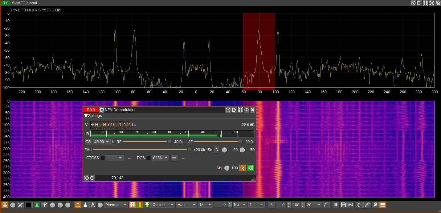
The thing is, I couldn't find good articles or anything to understand how the different channels are distributed. I know that stereo is AM modulated and that SAP is FM modulated. But which is which, I don't know, so I kind of guessed.
I found the SAP with the NFM block, which gave me the flag for Part 4: cucumber.
Then, still in NFM, on the next peak, the flag for Part 5: vertex (I don't know what it corresponds to).
Finally, with the AM block, we get the flag for Part 3: hologram, which I believe represents the stereo part. For this one, I struggled to get a clear voice, maybe due to the bandwidth limitation in AM on SDRangel.