In my very first project to receive satellite images, I built a V-dipole antenna. It’s very easy to make and produces convincing results.
The downside? All those gray interference bands on every image.
I tried countless fixes to remove them but to no avail, so I decided to switch to a quadrifilar antenna, or QFH (QuadriFilar Helicoidal). Let’s see if this solves the problem :)
The downside? All those gray interference bands on every image.
I tried countless fixes to remove them but to no avail, so I decided to switch to a quadrifilar antenna, or QFH (QuadriFilar Helicoidal). Let’s see if this solves the problem :)
How a QFH Antenna Works
The QFH antenna consists of two helical loops, each wrapped around a central axis and offset by 90°. For more on phase shift, check out this lesson.
Thanks to this phase offset, the helices produce circular polarization. Think of it as the "direction" of the electric field in our wave.
Thanks to this phase offset, the helices produce circular polarization. Think of it as the "direction" of the electric field in our wave.
Building the Antenna
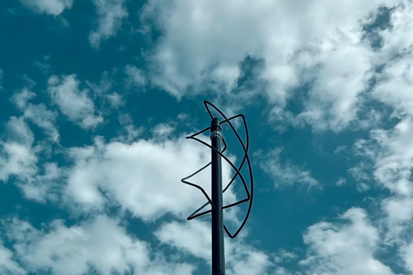
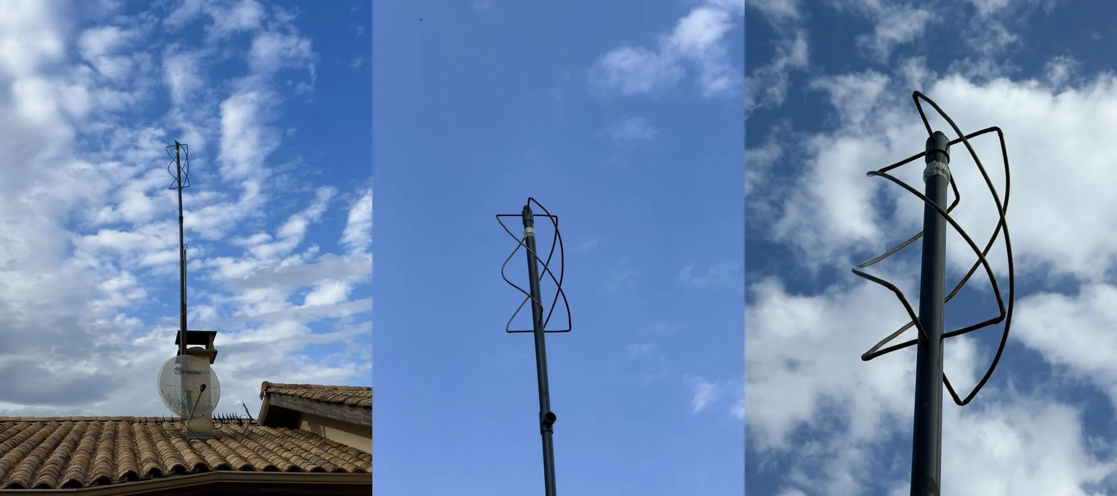
Keep in mind that your antenna will ultimately look like this (in 2D diagrams it might not seem that way):
Theory
To design the antenna, we’ll use this calculator.
- Design Frequency: I set it to
137.5MHzsince I want to receive satellite signals between137and138MHz. - Conductor Diameter: I use
9.5mmbecause I'll use a 3/8" copper tube (which is about9.52mm). Any diameter works, larger ones may broaden the antenna’s bandwidth and slightly reduce losses, but the gains are modest, so use what you have.
After filling in the defaults, click Calculate.
You’ll get an approximate schematic. Note the
You’ll get an approximate schematic. Note the
-0.5cm on the top 4 wires only, this ensures there’s enough space between them to join together.
DIY Build
Let’s start by listing the supplies (excluding tools). For the copper, I used spare copper crowns from air conditioning work. It’s annealed copper, so it’s very malleable. Sorry, the drawings are in French for now.

Top Section
To simplify the build, I used a PVC sleeve that we will place on top of the antenna.
You’ll need to drill 4 holes perfectly perpendicular around the sleeve. For that, head back to this site and scroll down to Generate a drilling template.
Fill in the outer diameter of the sleeve (
You’ll need to drill 4 holes perfectly perpendicular around the sleeve. For that, head back to this site and scroll down to Generate a drilling template.
Fill in the outer diameter of the sleeve (
58mm) and the copper tube diameter (9.5mm).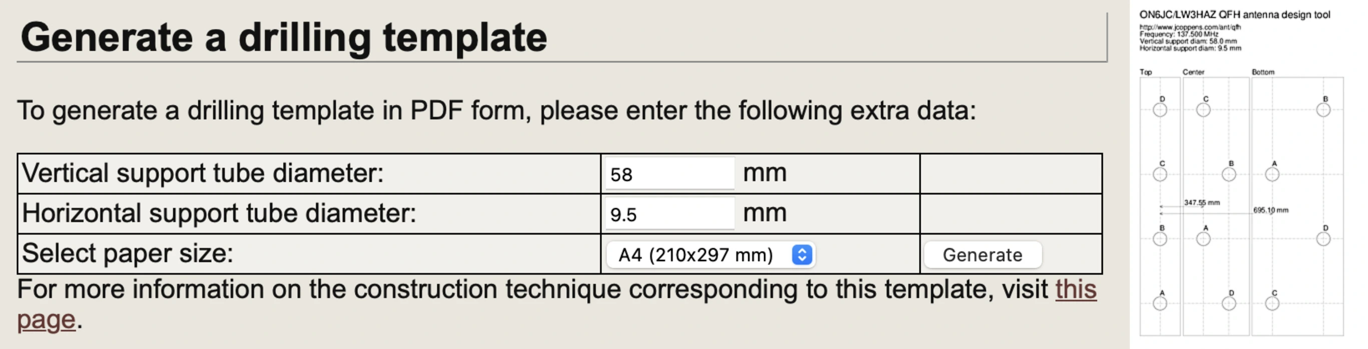
Wrap it around the PVC tube. It’s crucial that the paper exactly covers the tube’s circumference, an error of even
1mm can affect the alignment of the 4 copper rods. If it doesn’t fit perfectly, double-check your measurements.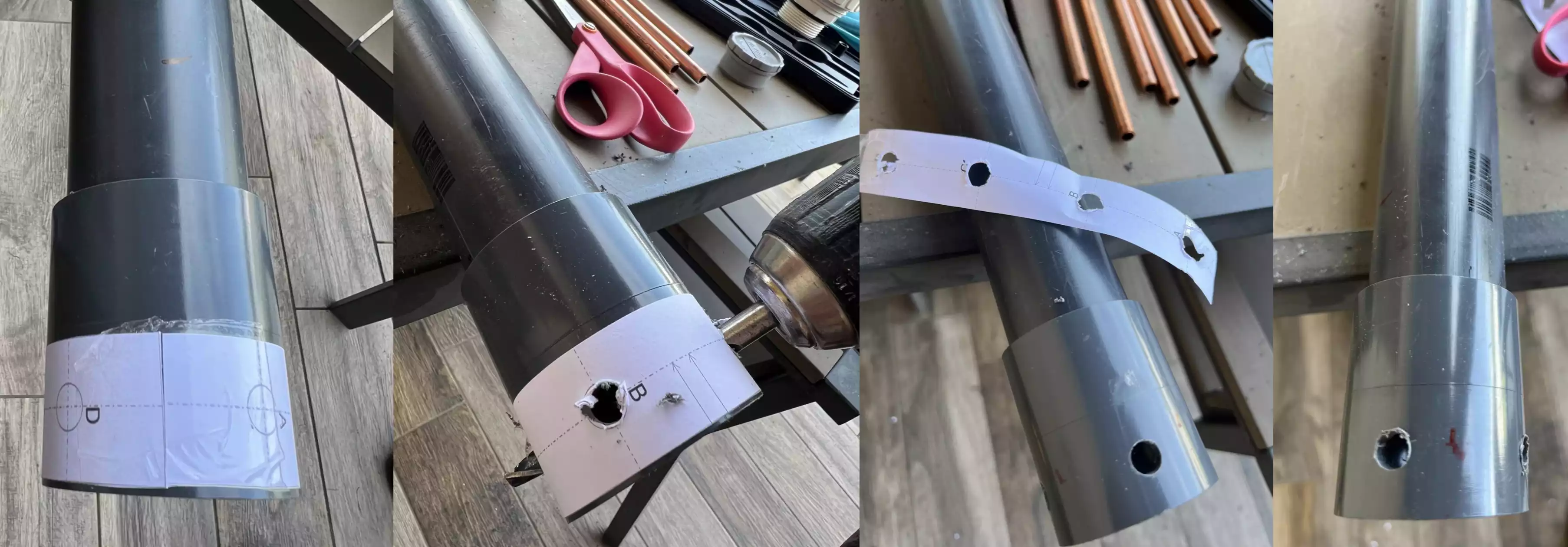
Bottom Section
Return to the Generate a drilling template section of the calculator. This time, use the outer diameter of the PVC tube (
52mm), be sure not to confuse it with the sleeve’s diameter used for the top.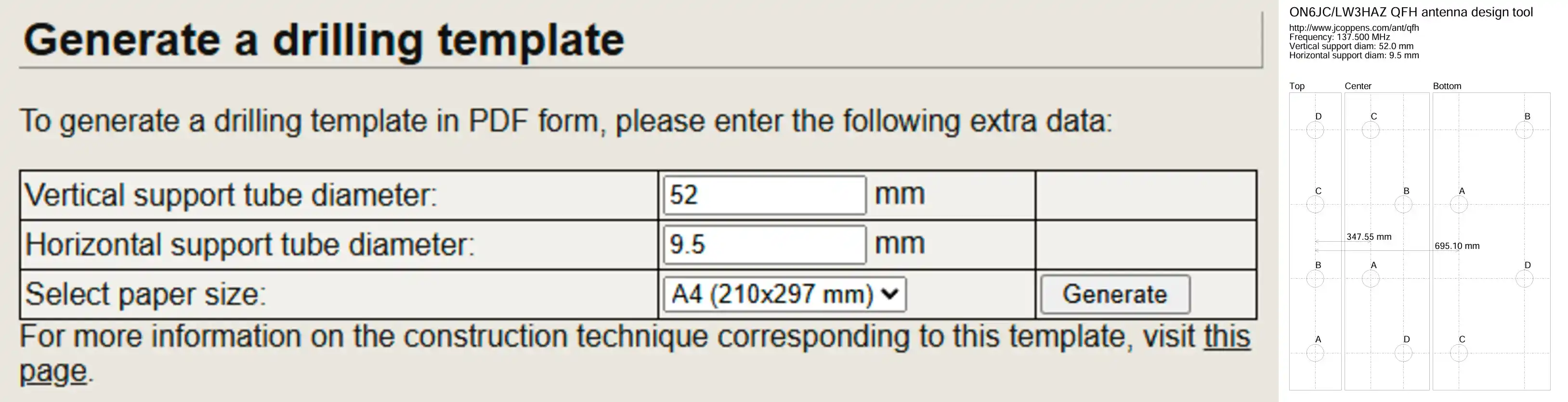
To know where to place it, note the value
695.10mm on the template, this represents the distance from the top wires to point A (essentially, the H2 distance on the antenna diagram).Bending the Tubes
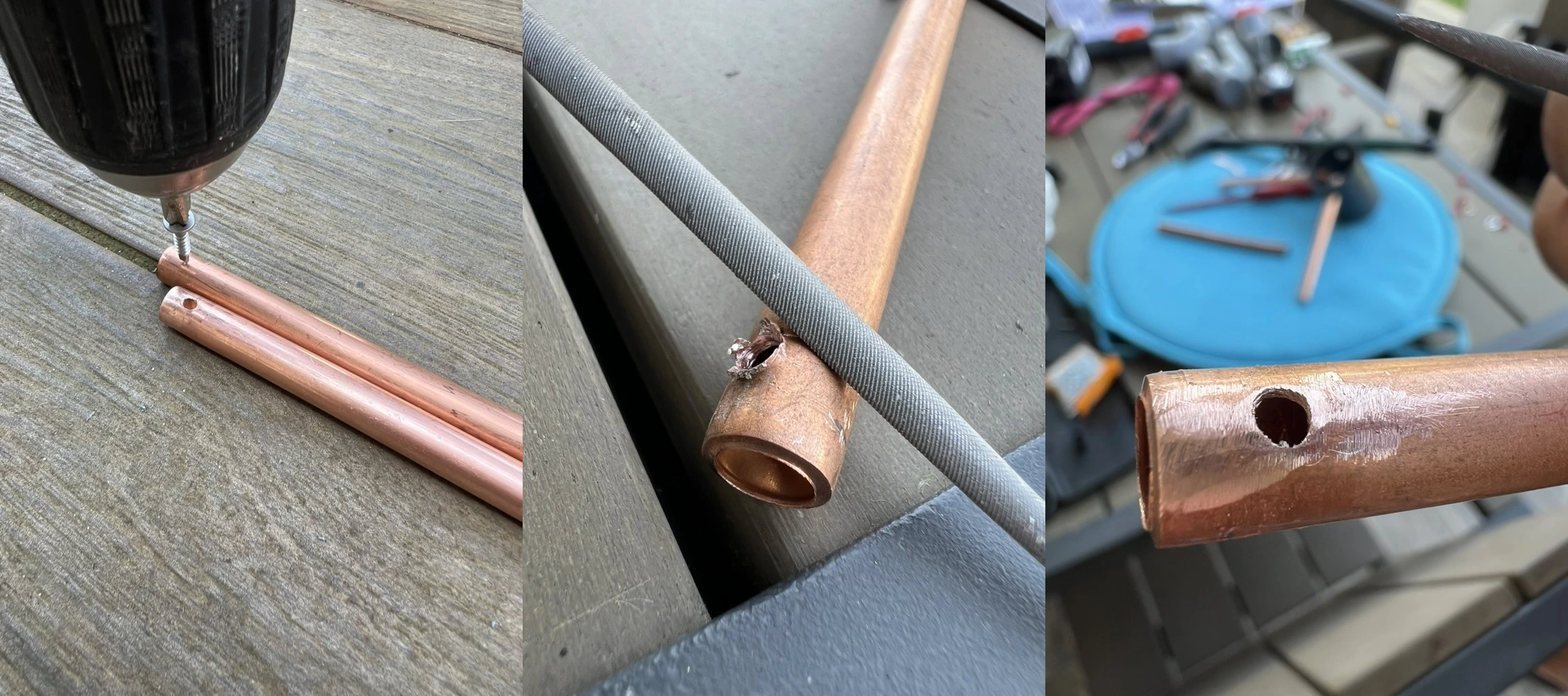
You can loosely position the elbows (without fixing them) at the end of each of the 4 long copper rods, either on the top or bottom of the antenna, the goal is to form a smooth curve. You might need to tighten the elbows slightly to prevent slippage while bending.
For bending, several techniques exist, in my case, I did it manually following this principle:
For bending, several techniques exist, in my case, I did it manually following this principle:

Alternatively, you can clamp the elbows tightly with the tube. The contact may not be perfect, but it works in a pinch.
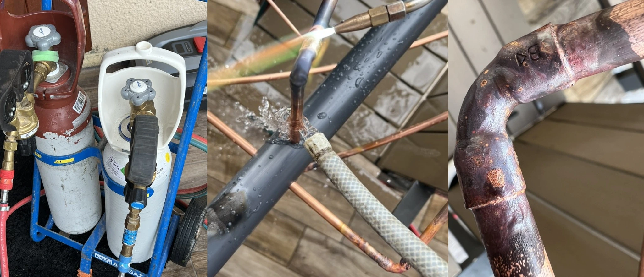
Balun
Now, we’ll drill 2 holes at the top of the tube to create a balun.
The signal converts into current in one branch in one direction and in the other branch in the opposite direction, meaning the current is balanced in the antenna.
However, in a coaxial cable, the current travels only in the center, making it unbalanced. The outer braid is tied to ground and serves as a shield to prevent the cable from acting as an antenna (and to protect the signal).
If left uncorrected, some of the received signal will go to ground, causing significant losses.
A balun converts from balanced to unbalanced (or vice versa), resolving this issue.
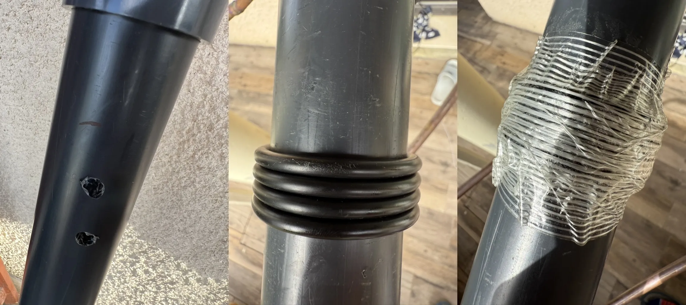
50Ω), and the second “1” is for the unbalanced side (the cable, also 50Ω). In a 1:1 balun, these two impedances are equal.The choice of 4 turns is not absolute but appears optimal for VHF waves.
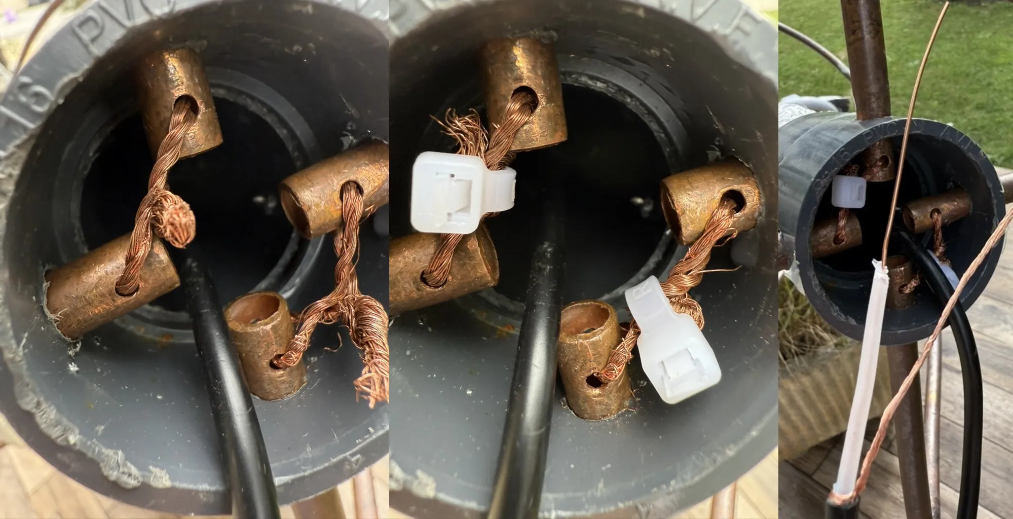
Wiring
There are several ways to connect the rods. Here’s a schematic of the proper wiring:

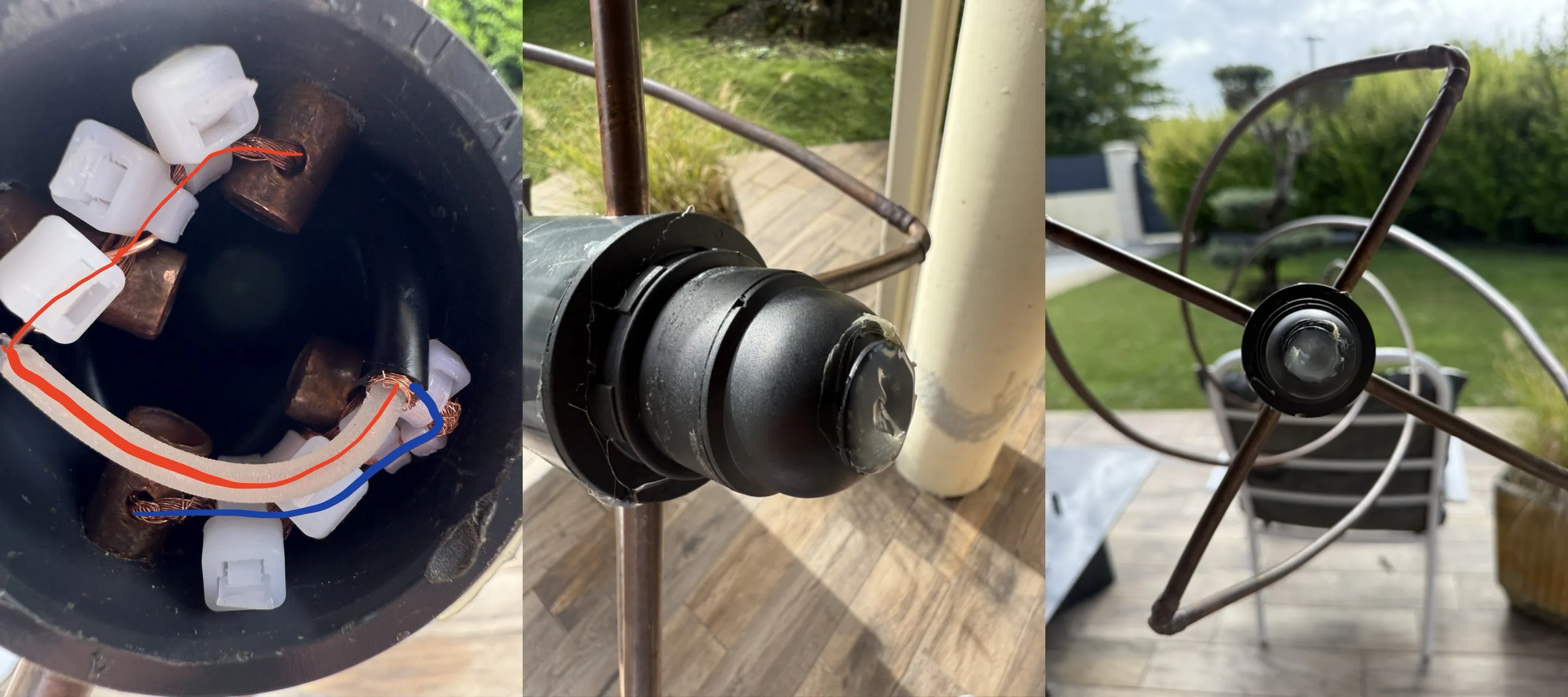
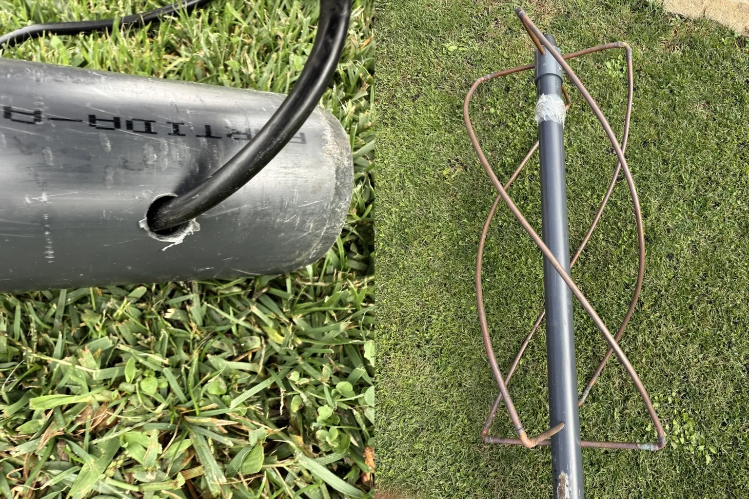
Installation
I drilled a small hole at the bottom of the tube to let the cable exit, this prevents it from being crushed when laying the antenna flat.
Testing
Now, let’s check its performance using an antenna tester. Although these values are mostly useful for transmission, they help verify if our antenna is well tuned.
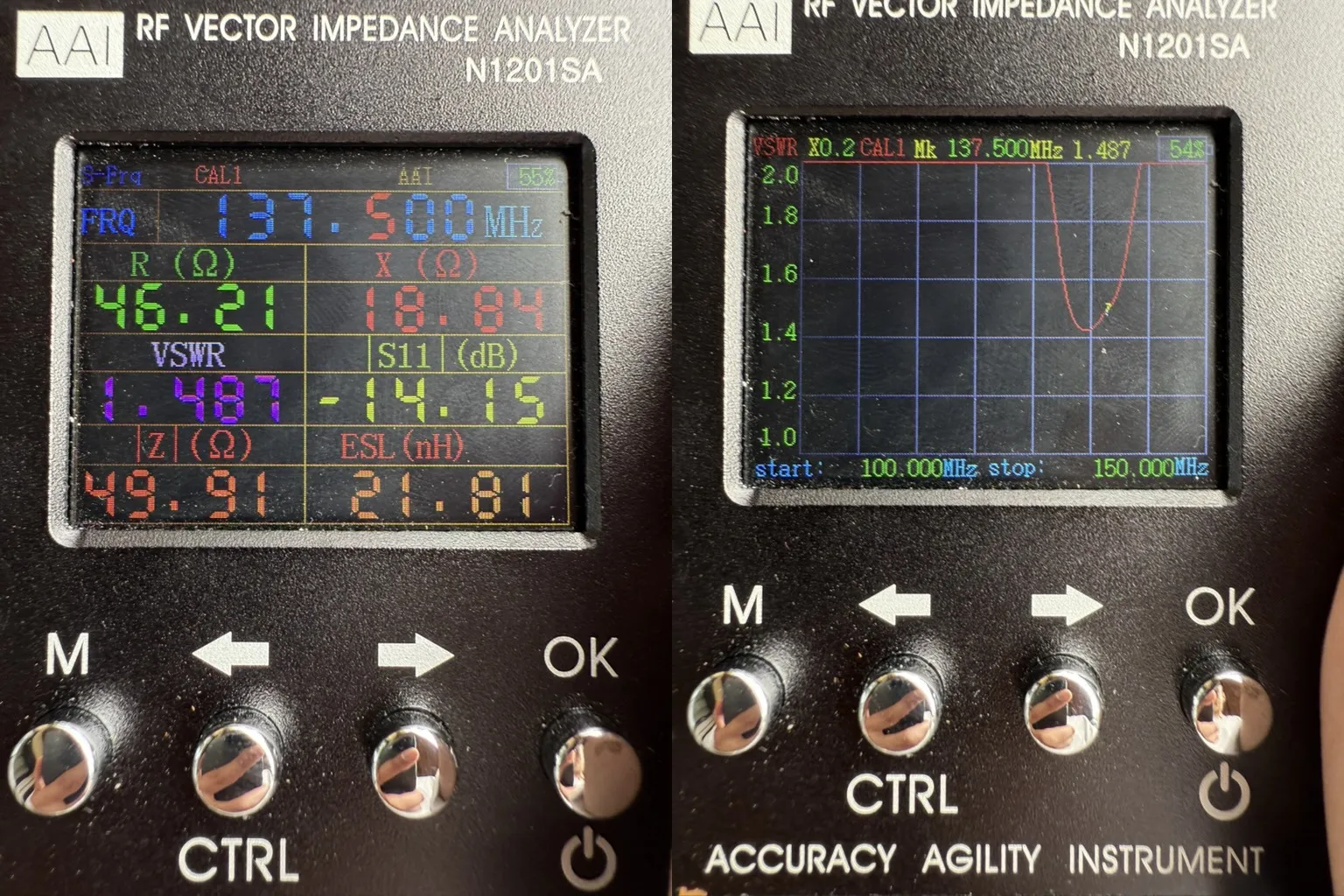
1.487, which is excellent for a DIY QFH antenna, anything <1.5 means it’s well calibrated.The impedance of
46.21Ω is also very good, as it’s close to the desired 50Ω.Finally, here’s the output the antenna provides:
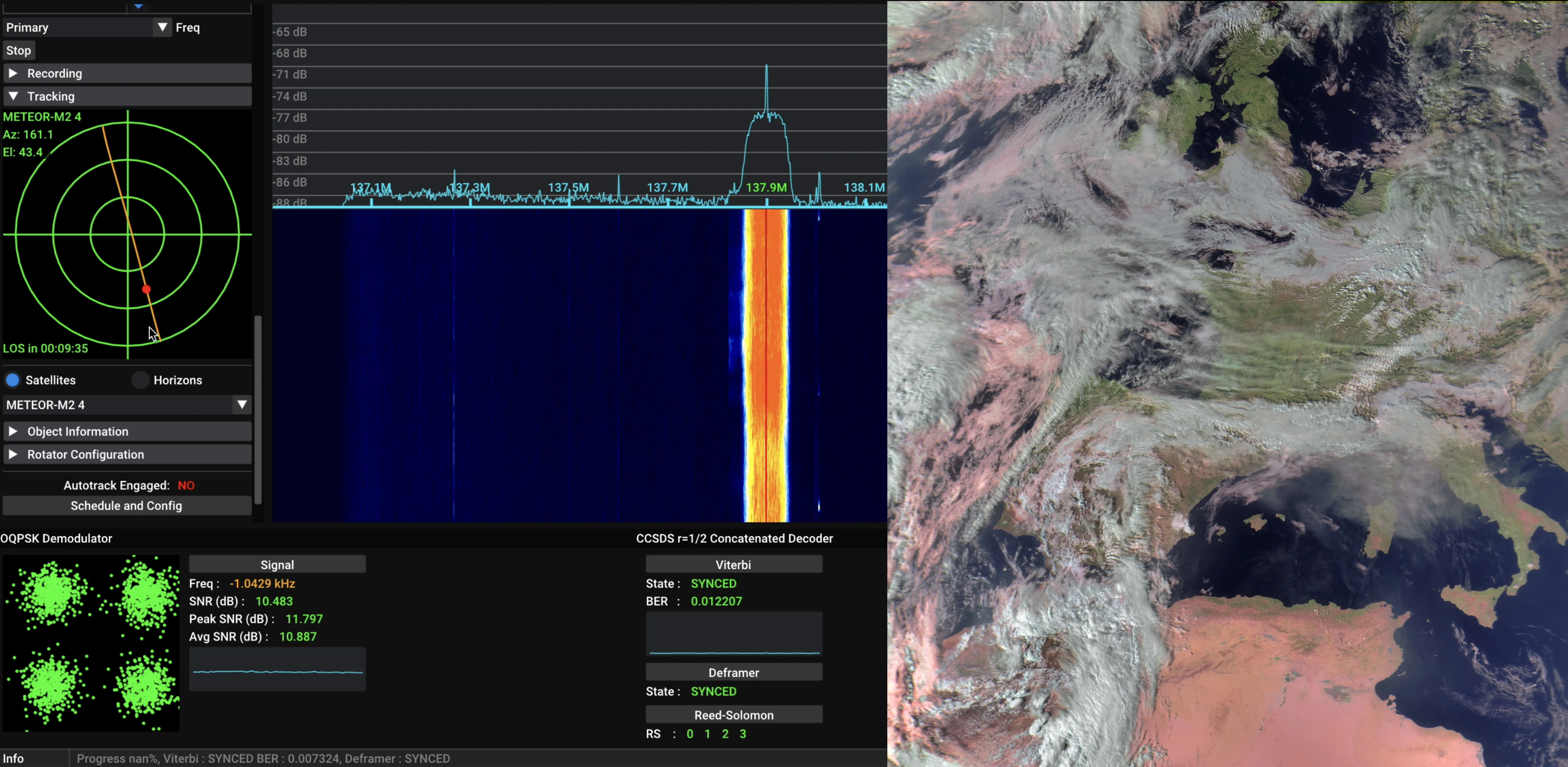
Concerning the original interference issue, my images now show (almost) no interference! Check out some examples in my gallery.